
By Mike Sokol
What follows is the first in a 12-part series about basic electricity for RV users and how to protect yourself and your family from shocks and possible electrocution.
Pre-Electricity
I can remember teaching myself basic electricity when I was 12 years old. It seemed like such a mysterious force that could do most anything from run a fan to shock you if you touched a wire. I wanted to know all about it. So for two years I read every book I could find in the library, every Popular Science magazine I could get my hands on and ran “electrical experiments” in my bedroom. By the time I was 14 years old I knew the basics of DC electricity and how it worked.
RV Safety
While RVs as wired from the factory are inherently safe, they can become silent-but-deadly killers if plugged into an improperly wired extension cord or campsite outlet. This is because RVs are basically a big cage of metal insulated from the ground by rubber tires. It’s up to you, the RVer, to make sure the frame and body of your RV is never electrified due to poor maintenance, bad connections, or reversed polarity in a power plug. This so called Hot-Skin problem is what causes a tingle when you touch the doorknob or metal steps of your RV while standing on the ground.
Just the Basics
There are some novel ways to think about and teach basic electricity to the casual RVer, enough so that you can learn how to test for and avoid shocks or potential electrocution at a campsite. There will be little or no math, no fancy schematic reading and certainly no memorization of formulas. It’s my privilege to teach you basic electricity safety as long as you do one thing for me — let me know if the information is making sense and is helpful to you. So after reading this post on RVtravel.com, head over to NoShockZone.org and give us some feedback, good or bad. The failure of the student to learn is the failure of the teacher to teach, and I take my teaching job seriously. So feedback is encouraged.
Why Do We Get Shocked? (What is This Volts Thing?)
What’s so hard to understand about electrical shocks in general is that they don’t seem to happen for any obvious reason. For instance, you can watch a pigeon on a power line that’s not being shocked, yet sometimes touching a power tool yourself while standing on wet ground can bring you to your knees. Just why is that?
Well, the first thing to understand about electricity is the concept of Voltage. Think of Voltage as electrical pressure, just like the pressure in a tank of water. Now in a tank of water we measure pressure in something called PSI (pounds per square inch), which will of course increase if we get a deeper tank. So while 10 PSI of water pressure from a short tank might give you a trickle of water when hooked up to a hose, 100 PSI of water pressure from a really tall tank gives you stream that will spray much further.

Water — and electricity — tries to flow to the side of least pressure. You can imagine that if a pipe is connected between two tanks with exactly the same water level and pressure (say, 100 PSI) there will be no flow of water through the hose. It just sits there and does nothing because the system is equalized. However, if you connect one tank with 100 PSI of water pressure to another tank with 10 PSI of water pressure, water will flow from the high tank to the low tank. We measure this water flow in gallons per minute.

Under Pressure
The same thing happens with electricity. You’ve often heard of “completing an electrical circuit,” but think of it as different electrical pressures. Getting back to the pigeon on the power line, if both of the bird”s feet are on the same wire, they’re at exactly the same electrical pressure. Because they’re at the same pressure, there’s no electrical current flowing through the bird. If, however, the pigeon is unlucky enough to touch one foot on a power line and a wing to the grounded metal power pole, then his one foot will be at 1,000 volts (think PSI of water pressure) and his wing at 0 volts (think an empty tank). This will cause a lot of current to flow through the bird, which we’ll measure in Amperes. And indeed 1,000 Volts across a pigeon can cause a bird explosion.
Now, consider your RV. Sometimes you may feel a shock when you touch your hand on the doorknob, and sometimes not. What’s happening is that there’s an electrical voltage (think pressure) on the body of the RV, which is waiting for some different electrical voltage level to head towards. If your entire body is inside the RV, then like the pigeon every part of you is at exactly the same voltage. And like the pigeon, there’s no current flow and you feel no shock. However, if one of your feet is on the ground at essentially zero volts and your hand is on the door of your RV that is at 100 volts, you become the pipe and the different electrical pressure (Volts) will push current (Amps) through your hand, arm, chest cavity, torso, leg and foot. If your foot is on dry ground there might be so little flow that you might not even feel it. But stand on the damp ground with a wet shoe, and you’ve made a zero voltage connection to the ground with your foot and a lot of current will flow through your body.
 Watch the Heart
The dangerous part is when this electrical flow goes through your chest cavity since right in the middle of you is your heart, and hearts don’t like to be shocked. That’s because the beat of your heart is controlled by electricity, which comes from your own internal pacemaker. And just like a clock radio can be scrambled by a nearby lighting strike, even a small amount of electrical current passing through your heart can cause it to start skipping beats and cause a heart attack. Just how little? Glad you asked.
I’m sure by now you’ve seen the 20-Amp marking on a circuit breaker. That means it can supply 20 Amps (Amperes) of current flow when asked to do so. Again, you can think of it as gallons per minute of flow, and Amps are indeed a count of electrons per second flowing through a wire (think pipe). Much more on that later, but it takes less than five milliamps of current to cause your heart to go into fibrillation mode. That’s just 5/1000 of an Amp or 0.005 Amps of alternating current to cause what’s essentially a heart attack. It takes just 30 Volts of Alternating Current (AC) to stop your heart if your hands and feet are wet. On the strange but true side of the coin, while Alternating Current is what causes your heart to go into fibrillation and stop pumping blood, the rescue crew will use Direct Current (DC) of several hundred Volts to reboot your heart and get it beating regularly again. That’s what they’re dumping through the paddles on your chest — Direct Current from big capacitors like you see charging on the TV dramas. “Clear!”
Stay Safe
The first rule of staying safe from electrocution is to keep your heart out of the current flow. You can see that getting shocked from hand to hand or hand to foot is about as bad as it can get. That means if you’re plugging in your RV plug to a campsite receptacle with one hand, the last thing you want to do is hold onto the metal box with your opposite hand or be kneeling on the wet ground. If you have two points of contact and something goes wrong (like you touch a bare wire), the current will flow to your opposite hand or feet, passing through your heart in the process. So always turn off the circuit breaker when plugging or unplugging your campsite power. Not doing so is to invite death by electrocution, and nobody wants that.
Quick Tips
•Use only one hand to plug or unplug any power cables
•Turn off breakers in the pedestal before plugging or unplugging campsite power
•Never stand or kneel on wet ground while making electrical hookups
•If you feel a shock from the doorknob of your RV, do not get into your RV. Shut off the pedestal circuit breaker immediately and alert the campsite manager.
Part 2 of this series will cover how to measure voltage at the campsite pedestal before plugging in. Stay tuned and stay safe.
****
Read all the segments in this series.
 Mike Sokol is the chief instructor for the HOW-TO Sound Workshops (www.howtosound.com) and the HOW-TO Church Sound Workshops. He is also an electrical and professional sound expert with 40 years in theindustry. Visit www.NoShockZone.org formore electrical safety tips for both RVers and musicians. Contact him at mike@noshockzone.org .
Copyright Mike Sokol 2010-2016. All Rights Reserved
##RVT761
 The Meter
 Before you graduate to measuring the big 240-Volt, 50-Amp outlets, you need to start on a common 120-Volt, 20-Amp outlet like you might find in your living room or throughout your RV. Here’s what one looks like and the connections as standardized by the National Electrical Code. You’ll see a little U-shaped hole: that is the Ground; a taller slot on the left, which is the Neutral; and a shorter slot on the right, which is the Hot connection. Don’t be confused if the receptacle is mounted upside down with the ground connection to the top. The taller slot is always the NEUTRAL, and the shorter slot is always the HOT.
 Hot to Neutral
 If hot-to-neutral checks out around 120 volts, then it’s time to test the ground, so plug your two meter leads into the HOT (shorter slot) and GROUND (U-shaped hole) connections. Since you’re reading from the Ground connection, which should be 0 volts and the Hot connection, which should be around 120 volts, your meter should show about 120 volts. If you read 0 or something strange such as 60 volts, then the ground wire might be floating, which could cause a hot-skin condition that will shock you when touching the body of the RV.
 Neutral to Ground
 Final Exam
 The first thing you need to note is the orientation of the ground lug on both sockets. Last week we used a 20-amp outlet for an example with its U-shaped ground lug at the bottom, while in this picture the ground lug is at the top. That was not a mistake, as most home outlets are wired with the ground at the bottom, and most electrical panels are wired to more recent code with the ground at the top. It doesn’t really matter which way the socket is wired as long as you keep your own head right-side-up. So if you’re looking at an upside-down outlet, turn the illustration upside down to match the outlet.
 If you remember our water tank example from Part I: the taller the tank, the greater the pressure. And since voltage is really electrical pressure, the same idea holds true. Look at the tank on the left and imagine you’ve got a pressure gauge that reads the difference between two pipes. So if you read between the red pipe at the top and the black pipe at the bottom, your gauge (or meter) will indicate the full pressure, which is in this case 240 PSI (Pounds per Square Inch). However, if you hook up the gauge (or meter) from a center pipe to ether the top or bottom pipe, it will indicate exactly half the pressure, which in this case is 120 PSI. The exact same thing happens at the power transformer on the pole feeding into your house or RV site. You really have 240 volts available, but there’s a center tapped transformer rather than a pipe. So if you connect a meter (or appliance) between the Red and Black wires, it will receive the full electrical pressure, which is 240 volts. But pick only the Black or Red “hot” wire and hook the other side of your meter or appliance to the center-tap White “neutral” wire, and you’ll have exactly half of the full voltage, which will be 120 volts.
 Take a look at the illustration on the left. You’ll see a standard 120/240-volt, 50-amp receptacle as found in many campgrounds. Look at the illustration on the left and you’ll see that the slots are placed like a little baseball diamond. If it’s oriented according to code with the U-shaped ground at the top, then follow along. If you plug your meter probes from Home plate (Neutral) to 1st base (Hot 2) you should read around 120 volts. From 1st base to 2nd base (Ground) you should also read about 120 volts. From second to third base (Hot 1) should read approx 120 volts, and finally from 3rd base back to home you should read approx 120 volts. Now, from home plate to 2nd base you should read close to zero (0 to 2) volts, and from 1st base to 3rd base you should read between 230 and 240 volts.
 Hot Skin
 Insulation
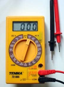 Using a Meter
 Ready… Set… Test…
 To test for an RV Hot Skin just turn on the non-contact tester by pushing the power button quickly, which will begin to blink once every few seconds to show you it’s on. Then confirm the tester is working properly by poking it into a hot blade of the power outlet on the pedestal. It should beep at you and blink if all is well. Now, gripping the tester firmly in one hand while standing on the ground, move the plastic tip until it’s touching anything metal around your RV. This could be an aluminum screen door, the exterior of an Airstream or the steel of the trailer hitch. With a non-contact tester you do not have to punch through the layer of paint, rust or plastic. If your RV has more than 40 volts on the skin, the VoltAltert will light up and start beeping at you, even from an inch or more away from the surface of the RV.
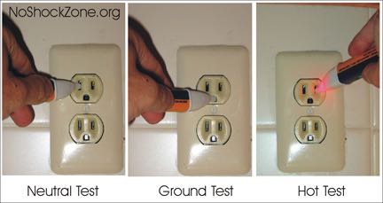 Outlets Re-visited
 What’s an Ampere?
 Small Hoses
 Big Wires
 Little Wires
 Size Me Up
 without overheating.
 What’s This Voltage Drop Thing?
 Big Pipes Equal Small Pressure Loss
 Small Pipes Equal Big Pressure Loss
 Big Wires
 But now we’ve cheaped out and installed far too skinny of an extension cord from the generator to the heater outlet. And any time we try to pull a significant current flow (let’s say, 10 amperes) down the skinny wire, there’s a lot of resistance to that flow, causing us to lose electrical pressure (voltage) just as we lost water pressure when using the pump with too-small of connecting pipes. In our generator illustration above there’s a 10-volt drop in the black wire and a matching 10-volt drop in the white wire. That leaves our heater with 110 volts on the bottom feed and 10 volts on the top feed. Again, our meter and heater element only care about the voltage differential applied to them, so it’s only working with 100 volts.
 Get to Work
 But put in a larger hole and there will be a lot more water flowing since there will be less resistance to current flow. And, of course, all that extra current can be used to do even more work.
 The turbine won’t be spinning very fast and can’t do much work. However, plug in something with a low resistance (large hole) to current flow like the right side of the illustration, and a lot more current will flow. In this case the turbine will spin much faster and can do much more work.
 Inventor Alert
 Measure It
 Breaker, Breaker…
 GFCI?
GFCI? How Does a GFCI Work?
 Out of Balance
 Teeter Totter
 Putting It All Together
 It’s All About Balance
 Nuisance Tripping
 You can do this ground fault leakage test by sacrificing a short extension cord to make a test cable. (Don’t you feel like a scientist, now?). With the extension cord unplugged from everything, just slit off the outer covering, being careful not to nick the insulation of the black, white or green wires.
 This allows you to plug your appliances one at a time into a non-GFCI outlet using your test cable to see how much current is leaking back to ground. Clamp the ammeter around the black (hot) and white (neutral) wires as shown in the picture, keeping the green (ground) wire out of the jaws. Your ammeter will now be registering how much current is going out the black wire minus how much is coming back the white wire. So any currents you read on the meter will be the ground leakage that can cause the GFCI to trip from that appliance.
 Note that there’s going to be a certain amount of leakage to ground from anything plugged into a wall outlet. So 1 mA or so is not a problem. In this case I have 0.0008 amps which is 0.8 mA of current flow, just less than 1 mA. That by itself shouldn’t cause a GFCI to trip. But you can see that if you have five appliances plugged into a single GFCI (like a campsite 20-amp receptacle) and each one is leaking around 1 mA of current to ground, then that GFCI breaker is going to trip whenever it feels like doing so.
 he solution is a
  Reduces noise
 As an added benefit, the noise made by the gases discharging from the generator exhaust pipe is diverted upward, above the roof line of the coach. As a result, in most installations, the exhaust system is actually quieter with the Gen-turi installed.
 LifeHammer’s Original Emergency Hammer is a high-quality car escape tool, designed to help prevent automotive entrapment after an accident. Should power locks become disabled or a safety belt jam after an accident, the double-sided steel hammer heads allow the vehicle occupant to shatter side and rear windows, while a safely concealed razor-sharp blade cuts easily through safety belts.