

Dear Readers,
After a brief respite last week, we’re now moving into Part 3A (which is actually part 4) of my 3- (actually 5-) part series on diagnosing short circuits. (Blame George Lucas and “Star Wars” for the numbering confusion). Today we’ll focus on troubleshooting short circuits on dead (unpowered) 120-volts AC RV electrical systems, and the next installment, Part 3B (which is actually part 5), will cover how to troubleshoot live 120-volt AC systems.
Reading a schematic
 If you want to get good at diagnosing short circuits, at some point you’re going to need to learn the basics of reading a schematic and predicting what you should read with a digital meter at various test points. There’s just no other good way to do this, so we’ll start with a simple example this week and show you the basics.
Here’s a simplified schematic of what the AC power distribution looks like in a typical 50-amp shore power RV. Note that there’s likely some kind of 4-wire inlet on the side of your RV. I’m showing a SmartPlug for clarity, but you probably have a twist-lock inlet installed in your own RV. More on that next week.
In any event, you can see that there are Hot-1, Hot-2, Neutral, and Ground connections coming into your RV. This first test must be done with all power turned off, but let’s see what brought us to the short circuit issue. I’m going to posit the scenario where the 50-amp double circuit breaker in your RV’s power distribution panel keeps tripping as soon as shore power is applied. Now this is a 50-amp double circuit breaker that’s going to trip both sides even if the problem is only on one of the legs. But how to figure out which leg? Well, enter the ohm meter.
MAKE SURE ALL POWER IS OFF AND YOU’RE UNPLUGGED FROM SHORE POWER
 First let’s turn off all of the 15- and 20-amp breakers in your RV’s power panel to isolate those gadgets that can fool this test. Only the main 50-amp breaker in your RV should be on, and you have to be completely disconnected from any AC power. And, of course, your shore power cord is disconnected from the side of your RV so you can access the contacts in the inlet directly.
Now, in this SmartPlug inlet you can see that the Neutral contact is at the top, the Ground contact is at the bottom, and the left contact is Hot-1, plus the right contact is Hot-2. To separate out the two Hots and identify which one is tripping both poles of the circuit breaker, all we have to do is measure the resistance between the Neutral contact and each Hot-Leg contact. So set your meter to its lowest ohm scale (usually 200 ohms) and touch your test leads first between Hot-1 and Neutral, as I’ve done in this picture (above). In this case the meter is indicating OL for Over-Load, which simply means the resistance is above 200 ohms. And that means the short circuit isn’t on that side of the 2-pole breaker.
 Next, meter between Hot-2 and the Neutral and measure the ohms. In this case we’re now reading 00.6 ohms, which is very close to a dead short (called continuity), and that’s what’s causing the main 50-amp circuit breaker to trip whenever shore power is applied. It doesn’t measure an actual zero (00.0) ohms because everything from your meter leads to even those heavy wires inside of your RV contribute a small amount of resistance. So we’ll consider anything under 1 ohm to be continuity, or a direct short circuit.
Since you’ve got continuity on the Hot-2 side, you can eliminate all of the wiring connected to the Hot-1 side of your electrical system. Also, many meters have a diode-test/continuity function which will beep or buzz as long as there’s continuity (a short circuit). So you can use alligator clips on your meter leads and let the meter stay out near the inlet plug while you start tugging and wiggling any wires inside you can access while listening for the beep to stop. If the beep comes and goes when you wiggle a wire or outlet a particular way then you’ve found the Hot to Neutral short.
That was a little too easy…
But let’s make this a little more complicated and find that there’s no short (continuity) between Hot-1 and Neutral, or Hot-2 and Neutral. What does that suggest? Well, as you can see in the schematic, the incoming Ground and Neutral wires are isolated from each other (which you can prove by metering between the Neutral and Ground contacts on your inlet), then you must have a Hot-1 or Hot-2 to Ground short somewhere. Prove it by metering between the Ground contact and Hot-1 or Hot-2. If you find that one of them shows a continuity reading (less than 1 ohm), then that’s the culprit.
 But what if you’re not tripping the main circuit breaker, but instead one or more of the 20-amp breakers is tripping? Then disconnect or shut off everything plugged into the outlet on a circuit breaker, then meter between the incoming Hot-1 and Neutral, then Hot-2 and Neutral, while someone flips on each of the 15-or 25-amp circuit breakers one at a time. Remember, there must be no AC power applied for this test – you’re only using the ohms scale on the meter so it’s safe to touch these wires with your hands. That won’t be the case next week when we do live AC testing.
What you should see is the meter indicate continuity when the problem circuit breaker is turned on, and go to high-ohm Over-Load mode when the offending breaker is off. Once that happens you can put the ohm meter in continuity beep/buzz mode then start twisting and flexing wires one at a time until the ohm meter beeping stops.
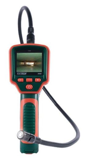 Now this could easily be a wire pinched next to the metal frame inside of the wall, or even a screw/nail through a wire, so you may need a Bore Scope camera to find it. I have a stupid-expensive medical Bore Scope camera that can poke into an artery and be threaded into your heart, but you can get a basic scope that will fit in a 1/4″ or 1/2″ access hole for less than $75. And many of them will connect to your smartphone so you can record a video of the inspection – which is very cool.
This gadget will allow you to see right inside of the walls (after drilling a small inspection hole), and find the problem wire that’s shorting out somewhere. Again, if you read continuity between Hot-1 or Hot-2 and Neutral, then it’s a line-to-neutral short circuit. But if you read continuity between Hot-1 or Hot-2 and the Ground contact, then the short circuit is between one of the 15-or 20-amp wires and the chassis of the RV. After you find the problem area it’s basically a blacksmithing problem where you cut a small access hole in the wall and repair the shorted wire.
But much more on picking Bore Scopes and repairing wires next week when we dive into short circuit testing with the power on. See you then.
In the meantime, let’s play safe out there….
![]()

Mike Sokol is an electrical and professional sound expert with 50+ years in the industry. His excellent book RV Electrical Safety is available at Amazon.com. For more info on Mike’s qualifications as an electrical expert, click here.
For information on how to support RVelectricity and No~Shock~Zone articles, seminars and videos, please click the I Like Mike Campaign.
##RVT934
Hi Mike. I just wanted to say that your simple schematic seems to differ from your pictured meter demonstration. Your metering pictures show the neutral at the top but the schematic has it at the bottom. Quote “Now, in this SmartPlug inlet you can see that the Neutral contact is at the top, the Ground contact is at the bottom,” Is this correct? or am I missing something? Thanks.
Oops…. Some days I’m upside down. I’ll correct the diagram. Thanks for the heads-up. Now I know at least one person read this for content.
I just fixed it (I think). Please take a look and tell me if that’s clear enough. Also, I have no idea why our intrepid editor Diane didn’t catch my wiring mistake. (Hah).
“If you don’t make mistakes, you aren’t really trying.”
~ Coleman Hawking
Dang! I focus on the context and forget to “proof” the images and double-check that they match the description or vice versa. OY! Sorry! I’ll try to remember. (But I’m really good at finding an extra space between sentences. 😉 ) —Diane the not-so-intrepid editor at RVtravel.com
I really don’t expect our copy editor, Diane, to check over all my content for electrical correctivity (is that even a word?).
If it wasn’t before, it is now. 😀 —Diane at RVtravel.com
Thanks Mike. It makes sense now. After 30 + years in the aircraft maintenance business, clarity is a habit that’s hard to break. Cheers.
Bill, I really do try for 100% accuracy, but there’s lots things to double and triple-check in these articles. I appreciate anyone notifying me of silly or even blatant errors in the copy or diagrams. That’s the beauty of electronic publication vs. printed magazines. I’ve been writing for close to 40 years, so more than the first half of my writing career was in print. Sometimes I would see a silly mistake in an article that I wrote months before and had finally made it through the magazine printing cycle. At that point I could print a clarification or retraction in another edition that wouldn’t hit the streets for another 3 months, and there was nothing I could do about the 100’s of thousands of copies already out there. With electronic publication (WordPress, especially) I can make a change to the text or graphics in a few minutes, then update it on the server in a few seconds. I much prefer being able to correct any errors and update any graphics in real time.
Interesting article as usual. I always thought “OL” meant Open Loop but same concept.
Also, users should be cautioned. This procedure may not work if there is a transfer switch involved, AND, if you have an inverter, realize that just because it’s not plugged in doesn’t mean it’s not live!
If the power is off, and the generator is off, then a simple generator transfer switch usually defaults to shore power. But an EMS transfer switch waits until the 120-volt AC power is established before pulling in the relay. I’ll cover more of that in the next installment about testing for shorts with live AC power.
I’ve heard it as Over Limit, Over Load, and Open Loop from my telephone repair guys back when twisted pair analog audio was king. I guess we can pick whichever one we like. 😎
When you unplug all the devices in the circuits you’re testing and your meter still reads no resistance then it will be one of those devices that has a short. You’ll then have to test each one to see where it is. Under normal circumstances this will be the scenario….unless there was work done on the rv recently that resulted in a short.
Exactly right. Once you have a non-destructive way to monitor for a short circuit (no smoke test) then you can begin testing branch circuits and devices one at a time until you discover the culprit. Without that methodology all you (or the RV technician charging you $140/hr) are doing is a spray-and-pray kind of repair. And that gets expensive.
“Stupid expensive” is right if spending more than $75 on a borescope — I get 1080 (HD resolution) USB pipe inspection cameras for $2 (not a typo). No tiny onboard screen, but it works fantastic with a laptop or cellphone. You also get 15′ of cable to inspect pipes (like in the name), and a couple stiffer camera holder options (various wands and heads to move and point the camera inside a wall). At this price, I have several dedicated to purposes, so I don’t worry about chimney soot or sewer pipe-slime interfering with a crystal-clear picture for wiring when needed…
Wolfe, please keep your opinions about how much my gear costs to yourself. I have a medical grade endoscope for legal work that’s small enough to be sterilized and inserted into a leg artery, then threaded into your heart to watch it beat from the inside. So it’s about $3,000 complete, which helps explain why heart surgery is so expensive.
My point was that tiny camera technology has filtered down to the point where you can get a contractor grade borescope for way less than $100, especially if you can use your smartphone as the video screen. And they’re great for finding problems inside of walls without chopping holes everywhere.